



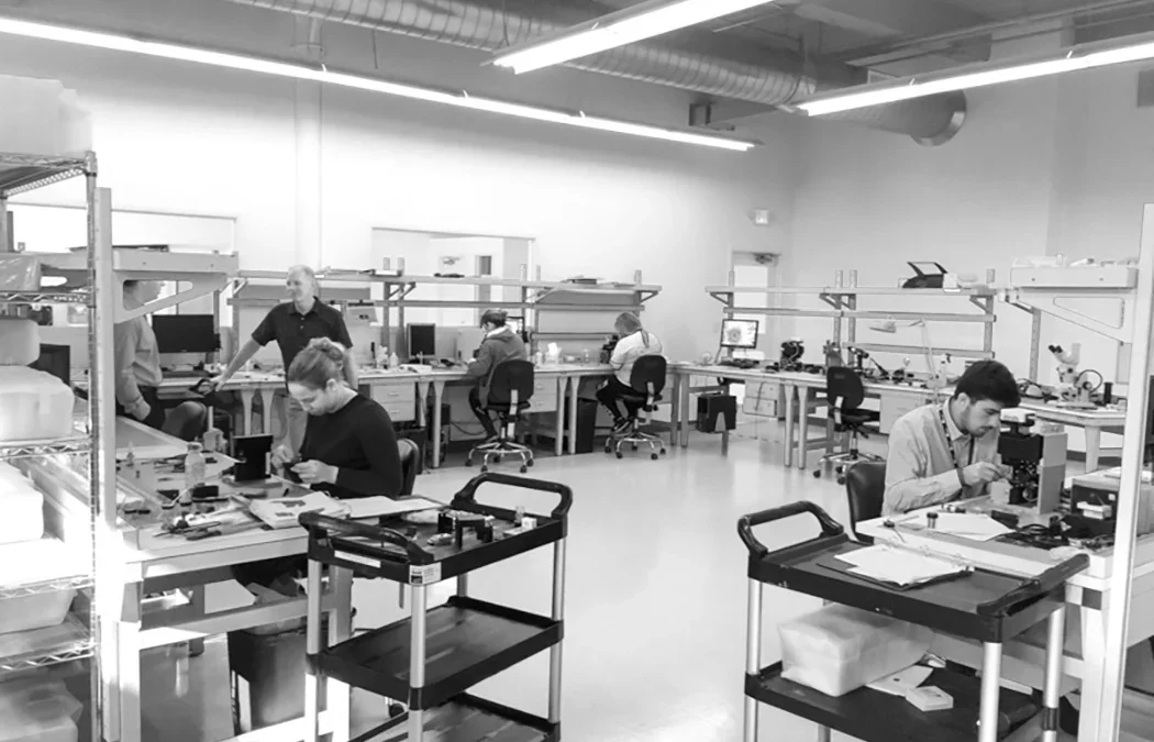
A collaborative robot is only one part of a production cell. The base, mounting plate, workholding, utility routing, operator interface, and service access around it determine whether the cell is straightforward to specify and maintain. Robotics infrastructure for cobot workstations is the engineered system that connects those pieces.
Talk to a Design Specialist about your robot mounting, workholding, and workstation requirements.
This guide is for facility planners, project and mechanical engineers, automation integrators, operations leaders, and EHS teams. It explains what to define before ordering a platform, how to review structural behavior, and when a standard bench is enough versus when the application needs a custom engineered solution. The goal is not to choose a base by appearance or catalog dimensions. The goal is to specify infrastructure that supports the robot, the process, the operator, and the next change to the cell.
What is robotics infrastructure for a cobot workstation?
Robotics infrastructure for a cobot workstation is the physical and technical foundation that lets a collaborative robot perform its assigned work in a defined cell. It includes the structural frame, robot mounting, fixtures, work surface, utilities, cable management, safety interfaces, operator supports, leveling, and service access. A complete specification connects those layers before fabrication begins.
The robot is not the whole work cell
The robot arm has a payload, reach, motion profile, controller, and end-of-arm tooling. None of those details automatically specify the platform below it. The workstation still has to carry the robot and process loads, keep interfaces aligned, provide clearance for the arm and tool, and route power, air, data, and pendant connections without creating trip, pinch, or service hazards.
That distinction matters because the infrastructure becomes part of the motion system. If the base shifts, deflects, or loses alignment, the robot is no longer operating against the conditions used during integration. The effect may appear as a calibration problem, an inconsistent fixture relationship, or a cell that requires more troubleshooting than expected. The correct response is to specify the workstation as part of the automation system, not as a secondary support.
Six layers to specify together
- Structure: frame stiffness, mass, squareness, joints, leveling, and floor interface.
- Mounting: robot plate, bolt pattern, orientation, height, and access for installation.
- Workholding: fixtures, tooling, bins, guarding interfaces, and clearances around the process.
- Utilities: electrical power, data, compressed air, exhaust where applicable, cable paths, and service loops.
- Safety: risk assessment inputs, emergency stop access, pinch and crush zones, maintenance access, and separation or safeguarding decisions.
- Human interface: operator reach, teach pendant position, monitor placement, lighting, material presentation, and clear walking paths.
Workplace Modular Systems positions Workplace TORQ as a robotics infrastructure line built around this first layer of the problem. The Workplace TORQ Bench is the current product form for the line, and the specification still starts with the application rather than the catalog.
What should you define before choosing the workstation?
Before choosing robotics infrastructure for cobot workstations, document the robot application, the loads created by motion and process tooling, the people who share the cell, and the physical limits of the installation site. Those inputs determine whether a standard platform can be configured safely or whether the cell needs custom engineering.
Start with the application, not the bench
Write down what the robot will do and how the task will run. A machine-tending cell, assembly cell, dispensing cell, inspection cell, and laboratory automation cell can place different demands on the same robot arm. The work may be repetitive or variable. The operator may load parts continuously or enter the cell only for changeover. The cell may be permanent, relocatable, or designed for a pilot that will later become a production asset.
- Application and process sequence
- Robot model, payload, reach, and end-of-arm tooling
- Fixture, part, and tool mass, including the highest expected combination
- Acceleration, deceleration, duty cycle, and stopping behavior supplied by the integrator
- Robot mounting orientation and required working height
- Operator loading, unloading, inspection, and changeover tasks
- Floor condition, anchors, leveling, mobility limits, and available footprint
- Power, data, air, exhaust, lighting, and other utility requirements
- Maintenance route, spare-part access, and future service clearances
- Required documentation, acceptance criteria, lead time, and installation responsibility
Separate static loads from dynamic loads
Static load is the weight the structure carries when the robot and tooling are at rest. Dynamic load includes the forces and moments created as joints accelerate, decelerate, reverse direction, or stop. Process forces can add another layer. A fixture may resist a part, a tool may press against a surface, or a workpiece may change the center of mass as it is picked or placed.
The workstation vendor should not be expected to invent the robot’s load case. The integrator or project engineer should provide the application envelope, then the vendor should show how the proposed structure and interfaces address it. This shared review is more useful than choosing a nominal weight capacity without documenting the motion and process conditions behind it.
Define the acceptance test before fabrication
Agree on what will be inspected after installation. The acceptance plan may cover level, squareness, mounting-hole location, access to utilities, alignment between robot and fixture, operator clearance, and documentation of any shims or field adjustments. If the cell must be moved, define how it will be located and rechecked. If the cell is permanent, define the floor interface and maintenance access before the frame is released.
Make the handoff measurable
A strong handoff records the approved robot and tooling configuration, the mounting interface, the final workstation location, the utility route, and the measurements taken at installation. It should also identify who owns any field adjustment and how a changed robot, fixture, or work surface will be reviewed. This record gives operations and maintenance a shared reference after the integrator leaves the site.
Do not make the document longer by adding generic specifications that no one will use. Make it useful by recording the decisions that affect the cell: what was measured, what was accepted, what can be adjusted, and what requires engineering review before a change. That is the difference between a catalog description and a deployment-ready infrastructure specification.
Book a Consultation when the application envelope, mounting geometry, or site constraints need an engineering review before quoting.
How do stiffness, squareness, and resonance shape the specification?
Stiffness matters because a robot workstation must resist both visible deflection and small changes at its interfaces. Squareness matters because the robot, fixture, and work surface are related coordinate systems. Resonance matters because a structure with a natural frequency near an excitation created by robot motion can amplify movement instead of simply carrying weight.
Static stiffness is more than a weight rating
A load rating answers one question: how much weight can the structure support under a defined condition? It does not fully answer how much the mounting surface moves when a robot reaches, turns, or applies a process force. A platform can carry a static load and still be a poor foundation if the frame, joints, leveling points, or floor interface allow too much deflection for the application.
Review the load path from the robot plate to the floor. The plate transfers forces into the frame. The frame transfers them through joints and supports. The leveling system transfers them into the floor. Every interface affects the result. A specification should therefore identify the robot mounting surface, structural members, joint method, levelers or anchors, and the floor condition that the design assumes.
Dynamic stiffness and natural frequency
Dynamic stiffness is the structure’s resistance to movement when the load changes over time. In a robot cell, the relevant input is not only the robot’s mass. It is also the motion of the arm, the acceleration of the payload, the change in direction, the tooling, the fixture, and the way a stop transfers load through the base.
Every structure has natural modes of vibration. When an excitation approaches one of those modes, the movement can become larger than the original input. The engineering objective is to keep the installed assembly’s natural behavior clear of the motion that the application excites. That is why the useful comparison is not simply steel strength versus aluminum strength. It is the stiffness, mass, joint behavior, geometry, and installed boundary condition of the complete assembly.
Compare infrastructure options by behavior
| Option | Structural question | Modularity | Planning implication |
|---|---|---|---|
| Welded steel sub-assemblies | Can the frame hold shape and resist changing loads through the full load path? | Connection points can be added where adjustment is useful. | Strong candidate when stiffness, mass, and repeatable geometry are central requirements. |
| Bolted extrusion frame | How will joint preload, fastener condition, and repeated vibration be checked over time? | High adjustment flexibility. | Useful when rapid reconfiguration is the main requirement, but joint behavior must be part of maintenance planning. |
| Repurposed worktable | Was the table designed for robot moments, tooling loads, and the floor interface? | Usually limited. | Do not assume a general worktable is a robot base because it can carry the static weight. |
| Custom weldment | Are geometry, documentation, service access, and acceptance criteria controlled? | Defined by the project. | Can fit a complex cell, but requires clear engineering ownership and change control. |
Workplace Modular Systems describes TORQ’s welded steel sub-assemblies as a stiffness and mass strategy intended to avoid resonance rather than absorb vibration. TORQ also retains aluminum extrusion connection points where modular adjustment is useful for integrators. That is a more precise claim than saying one material always solves every vibration problem. The installed geometry, robot, tooling, process, and floor still have to be reviewed together.
Joint design is part of the structural specification. TORQ uses serrated flange hardware to join sub-assemblies, with the connection intended to bite into the steel rather than rely only on bolt torque. The important question for any platform is how its joints behave under the actual load cycle, not whether the product description uses the word heavy duty.
For a broader comparison of robot-cell materials, the planned WMS cluster article on welded steel versus extruded aluminum can go deeper. This pillar should give the reader enough structure to ask better questions without repeating that article’s complete comparison.
What mounting, workholding, utilities, and interfaces are required?
A cobot workstation needs more than a flat surface. The mounting system must put the robot in the intended coordinate relationship to the work, while the workholding and utility interfaces keep the cell usable through installation, production, changeover, and maintenance.
Mount the robot for the task
Specify the robot plate, bolt pattern, orientation, height, access for fasteners, and relationship to the work surface. Workplace TORQ supports robot-specific mounting plates and direct mounting to the work surface, with orientation options selected to fit the cell. The correct orientation depends on reach, tool clearance, operator interaction, part flow, and the location of fixtures. It should be selected with the integrator, not treated as a cosmetic option.
Design the workholding around the process
Workholding includes nests, clamps, bins, trays, inspection surfaces, tool stands, and interfaces for the end effector. Mark the robot envelope and the operator envelope before fixing the work surface. The fixture must be reachable by the robot without forcing the arm into an avoidable extreme, and it must be accessible to the person loading parts or completing a changeover.
Also document what changes. A cell that handles one part today may handle a family of parts later. Leave deliberate locations for accessories and fixtures rather than drilling ad hoc holes into a structural member after the workstation is installed. This is where a robot-agnostic platform can help, provided the base is still specified around the actual application.
Route utilities for installation and service
List every utility before the frame is released: power, data, compressed air, exhaust where required, lighting, control cables, teach pendant, emergency stop devices, and any process-specific connections. Keep cables clear of moving joints, sharp edges, pinch points, hot surfaces, and operator walkways. Provide service loops that support the robot’s full motion without dragging on the floor or pulling against connectors.
WMS’s broader workstation portfolio includes vertically integrated utility chases on StandardPLUS platforms. On a robotics platform, the same planning principle applies: utilities should be part of the physical design, not an afterthought added with loose extensions and improvised clamps. Verify the final routing with the integrator and EHS team.
Review Workplace TORQ Robotics Infrastructure for the current robot workstation platform and available interface options.
How should safety and ergonomics influence cobot infrastructure?
A collaborative robot is designed for applications where people and robots may share a workspace, but collaborative operation does not remove the need for an application-specific risk assessment. Infrastructure should help the integrator and EHS team control the hazards created by motion, tooling, parts, utilities, access, and maintenance.
Use the cell layout to expose hazards
Mark pinch and crush points at the robot base, fixtures, drawers, utility paths, and adjustable components. Identify where an operator can reach into the cell, where a part can fall, and where a service person must place hands during setup or maintenance. Emergency stop devices should be reachable from the positions where a person loads, teaches, inspects, and services the process.
Do not assume that low speed or force-limited motion makes every tool safe. A sharp end effector, a hot process, a heavy part, a clamp, or a rotating tool can create a hazard independent of the arm’s collaborative settings. The integrator must validate the complete application, including tooling and process conditions.
Fit the operator to the infrastructure
Human factors include reach distance, working height, visibility, material presentation, monitor and pendant position, lighting, foot clearance, and the frequency of loading or inspection. A robot cell that is structurally sound can still fail operationally if the operator must twist around the base, reach over a fixture, or step across utility lines for every cycle.
Workplace TORQ provides three standard work heights with fine adjustment using leveling feet. Treat that range as a fit input, not as a substitute for an ergonomic review. The right height depends on the process, the part, the tooling, the operator, and whether the person works seated, standing, or alternates between tasks.
Plan for maintenance and changeover
Leave access to fasteners, cable paths, filters, sensors, fixtures, and the controller. Document where the robot can be safely isolated and where a technician can stand while making adjustments. If the workstation is mobile, define how it will be located and leveled again. If it is fixed, define the anchor and requalification process before installation.
Safety, ergonomics, and structural requirements are connected. A platform that forces an operator into a poor posture may encourage bypasses. A utility path that is hard to service may be rerouted through a hazard zone. A base that cannot be re-leveled may make a changeover harder to verify. Treat these as specification items, not commissioning surprises.
How do you plan the cobot work-cell layout?
Plan a cobot work cell by mapping the robot envelope, human envelope, material flow, utility paths, maintenance route, and floor interface before fixing the workstation footprint. The layout should make the intended motion and access visible to the integrator, EHS team, and facility owner before fabrication.
Map the process in sequence
- Place the robot base and mark the full working envelope, including tooling and payload.
- Place the infeed, outfeed, fixtures, bins, inspection points, and operator handoff locations.
- Mark the operator’s standing, loading, teaching, and maintenance positions.
- Route power, data, air, pendant, and process utilities without crossing moving or walking paths.
- Identify floor anchors, levelers, casters, locating pins, and any relocation sequence.
- Review guarding, separation, emergency stop access, and service clearances with qualified owners.
- Freeze mounting and utility interfaces only after the integrator confirms the cell can run and be maintained.
Use a coordination table
| Planning item | Owner | Evidence to review | Release decision |
|---|---|---|---|
| Robot and tooling | Automation integrator | Model, payload, reach, tooling, motion envelope | Mounting and clearance are defined |
| Structure and floor | Mechanical engineer and workstation vendor | Load cases, frame, joints, levelers, anchors | Base can be fabricated and installed as specified |
| Operator interaction | Operations and EHS | Reach, posture, access, stop locations, hazards | People can load, teach, inspect, and service safely |
| Utilities and service | Facilities and controls | Power, air, data, routing, loops, disconnects | Installation and maintenance paths are clear |
Design for the next change
Lifecycle planning is easiest before the first build. Note which interfaces may change if the robot, end effector, fixture, part family, or operator sequence changes. A platform does not need to promise universal compatibility to be useful. It needs defined interfaces, enough structural margin for the approved application, and documentation that allows the next engineer to understand what was specified.
The planned WMS layout spoke can provide detailed templates and clearance methods. This pillar should establish the review sequence so a reader can bring the right information to that deeper discussion.
When does robot-agnostic infrastructure reduce lifecycle risk?
Robot-agnostic infrastructure reduces lifecycle risk when the base, mounting interfaces, utilities, and documentation can accommodate an approved change without forcing the entire cell to be discarded. It does not mean every robot can be installed without a new review. It means the structural platform is not locked to one brand or one configuration by default.
Separate the base from the robot-specific interface
Workplace TORQ is described as robot agnostic and compatible with Universal Robots, FANUC, ABB, Doosan, Techman, and others. The robot-specific plate still matters. Its pattern, orientation, height, fasteners, cable routing, and load case must be reviewed for the selected robot. Robot agnostic is a design strategy, not a promise to skip engineering.
Document what can change
Capture the base dimensions, plate details, utility paths, leveling method, fixture locations, acceptance measurements, and approved load assumptions. Mark which parts are standard and which parts are custom. That record protects the next changeover from becoming a new discovery exercise.
Consider service and warranty
Ask who owns the engineering review, manufacturing, installation, and service response. WMS documents a lifetime warranty on its welded steel frame, casework, and powder coat, and a five-year warranty on work surfaces and ESD laminates. Warranty terms do not replace application review, but they are relevant to lifecycle planning and procurement comparison.
Where does Workplace TORQ Bench fit in the specification?
Workplace TORQ Bench fits applications that need a purpose-built, robot-agnostic foundation with welded steel sub-assemblies, defined mounting options, work-surface flexibility, and a domestic manufacturing path. It is the only currently available product in the TORQ Robotics Infrastructure line as of 2026, with manual height adjustment.
Specify the structure and interface together
TORQ uses welded steel sub-assemblies for stiffness and mass, with serrated flange hardware joining the sub-assemblies. The product retains aluminum extrusion connection points where modular adjustment is useful. The resulting specification can combine a rigid structural foundation with defined points for accessories and integrator adjustments.
Available planning inputs include robot compatibility, a robot-specific mounting plate or direct work-surface mounting, work height, leveling, utility routing, and the need for an assembled or knocked-down shipment. A knocked-down configuration is described as requiring approximately one-fifth of the assembly labor of an equivalent extrusion bench. Treat that figure as a product claim for the stated comparison, not a universal labor estimate for every cell.
Use the narrow, verified relationship language
Universal Robots purchased five TORQ units to use as infrastructure for its own product demonstrations. Describe that fact narrowly as a purchase for demonstrations. It does not establish any additional relationship status, so keep the statement bounded in customer-facing material.
Workplace Modular Systems was founded in 1950 in Londonderry, New Hampshire and designs, engineers, manufactures, and installs industrial workstations and robotics infrastructure. Standard domestic lead times are commonly stated as four to six weeks, subject to the approved configuration and order review.
Explore industrial workstation platforms when the project needs a broader workstation comparison, or review custom engineered workstation solutions when the application does not fit a standard configuration.
What should a workstation specification and vendor review include?
A complete workstation specification should allow an integrator, manufacturer, facility owner, and EHS reviewer to make the same decision from the same information. Use the following checklist in the request for information or request for quote.
- Application: process, parts, tooling, cycle, operator tasks, and changeover.
- Robot: model, payload, reach, end effector, motion envelope, mounting pattern, and orientation.
- Loads: static weight, dynamic motion, process forces, fixture loads, and stopping conditions supplied by the integrator.
- Structure: frame, joints, work surface, levelers, anchors, floor condition, and acceptance measurements.
- Utilities: power, data, air, process connections, cable routing, disconnects, and service loops.
- Safety: risk assessment ownership, stop locations, pinch zones, access, maintenance, and safeguarding interfaces.
- Ergonomics: work height, reach, posture, visibility, material presentation, lighting, and operator rotation.
- Lifecycle: robot changes, fixture changes, documentation, spares, warranty, relocation, and requalification.
- Delivery: engineering review, manufacturing location, lead time, assembly state, installation scope, and responsibility for final acceptance.
Use a standard configuration when the robot, dimensions, load case, utilities, and operator needs fit the documented platform. Ask for custom engineering when the cell has unusual geometry, high process loads, complex utilities, integrated guarding, unusual floor conditions, or a mounting relationship that is not represented by the standard options.
Ask the vendor to show the complete handoff
A useful quote response should make the boundary between the workstation and the automation system clear. Ask for the proposed frame and interface drawings, the mounting assumptions, the stated load case, the utility and service provisions, the shipment condition, and the installation responsibilities. If the vendor is relying on information from the integrator, those inputs should be listed rather than silently assumed.
Also ask how field changes are handled. A work surface change may affect reach. A different fixture may affect the center of mass. A relocated mobile platform may need a new level or location check. The best supplier relationship gives the project team a clear path to review those changes without treating every question as a new product search.
Request a Quote with the application and interface information your integrator has already defined.
Frequently asked questions about cobot workstation planning
What is robotics infrastructure for a cobot workstation?
It is the structural base, robot mounting, workholding, utility routing, safety interface, operator support, and service access that allow a collaborative robot to function as part of a complete cell. The specification should connect those elements to the application, floor, tooling, people, and maintenance plan.
Why does stiffness matter for a cobot workstation?
Stiffness limits movement and deflection at the robot mounting and fixture interfaces. Dynamic stiffness also affects how the installed structure responds to changing robot loads. A good review considers the complete load path, joint behavior, geometry, mass, leveling, and floor interface instead of relying only on a static weight rating.
Is welded steel always better than extruded aluminum?
No material is automatically correct for every cell. The decision should compare the installed structure, joint behavior, stiffness, mass, modularity, service plan, and application loads. WMS positions TORQ’s welded steel sub-assemblies around stiffness and resonance avoidance, while retaining modular connection points where adjustment is useful.
What does robot agnostic mean?
Robot agnostic means the platform is not designed for only one robot brand or model. It does not remove the need to specify a robot-specific plate, bolt pattern, orientation, load case, cable path, and acceptance check for the selected robot and application.
Should a cobot workstation be mobile?
Mobility is an application decision. A mobile platform needs a clear method for locking, leveling, locating, and rechecking the robot after movement. A fixed or anchored platform may be more appropriate when the cell requires stable geometry, repeatable positioning, heavy process loads, or controlled access.
When should an integrator or engineer be involved?
Involve the integrator or project engineer before the workstation is ordered whenever the robot motion, tooling, fixtures, utilities, safety, floor interface, or operator sequence is not fully defined. Early coordination helps the manufacturer design the base around the actual cell instead of correcting mismatched interfaces during installation.
What information should accompany a workstation quote?
Include the robot model, payload, reach, tooling, fixtures, process loads, mounting orientation, work height, footprint, floor condition, utilities, operator tasks, safety constraints, shipment needs, and target timing. A drawing or layout sketch is useful, but a written list of assumptions is just as important.
How do I choose a standard or custom workstation?
Choose a standard configuration when the application fits the documented dimensions, load case, interfaces, utilities, and operator requirements. Choose custom engineering when the cell has unusual geometry, high process loads, integrated guarding, complex utilities, unusual floor conditions, or a mounting relationship outside standard options.
Plan the foundation before the robot arrives
Robotics infrastructure for cobot workstations is a specification problem, not a finishing touch. Define the application, load path, interfaces, utilities, safety review, operator needs, and lifecycle plan before selecting the platform. Workplace Modular Systems can help with standard workstation configurations, Workplace TORQ Bench planning, and custom engineered solutions.
Talk to a Design Specialist or Request a Quote for the next step.